Ithaca High School Math Seminar Lesson 2-13
Date: 2023.12.12
In the last four lessons of this seminar, we will explore three-dimensional graphics. We'll begin this exploration by making the following animation of a tetrahedron from scratch (click to play).
Step 1: Draw some cubes
In the last couple of lessons we've written our own self-contained 2D graphics programs in Odin/raylib. Raylib also has very helpful procedures to help us make 3D graphics, some of which we'll use today.
3D graphics usually requires a virtual camera, which was something we didn't need to worry about in the 2D world. Camera code is extremely important, but something the vast majority of programmers are afraid to write (or even look into) because they think the mathematics involved is too complicated. In reality, the mathematics is just basic linear algebra, and therefore not nearly as bad as people make it out to be.
This said, camera code does take time to figure out and right from scratch (and certainly more time than the 47 minutes we have today). As such, we'll use raylib's camera procedures today to set up a 3D rendering environment, although we may look into this later in the course (time permitting).
Cameras in raylib are simple to define. We only need to specify:
- the location of the camera,
- where the camera points,
- which direction is up,
- the camera's field of view (fov),
- the type of projection the camera is doing.
Once these values are set, it rendering a scene in Odin/raylib is relatively simple.
package tetrahedron

import rl "vendor:raylib"

main :: proc() {
    rl.InitWindow(1000,1000,"Cube")
    defer rl.CloseWindow()

    camera1 := rl.Camera3D{
        position   = {2, 2, 2},
        target     = {0, 0, 0},
        up         = {0, 1, 0},
        fovy       = 45,
        projection = rl.CameraProjection.PERSPECTIVE,
    }

    rl.SetTargetFPS(60)

    for ! rl.WindowShouldClose() {

        rl.BeginDrawing()
        rl.BeginMode3D(camera1)
        rl.ClearBackground(rl.GRAY)

        rl.DrawGrid(10, 1)
        rl.DrawCubeV({0,0,0}, 0.5 * {1,1,1}, rl.BLACK)

        rl.EndMode3D()
        rl.EndDrawing()
    }
}
The code above, when compiled and ran, produces the following image.
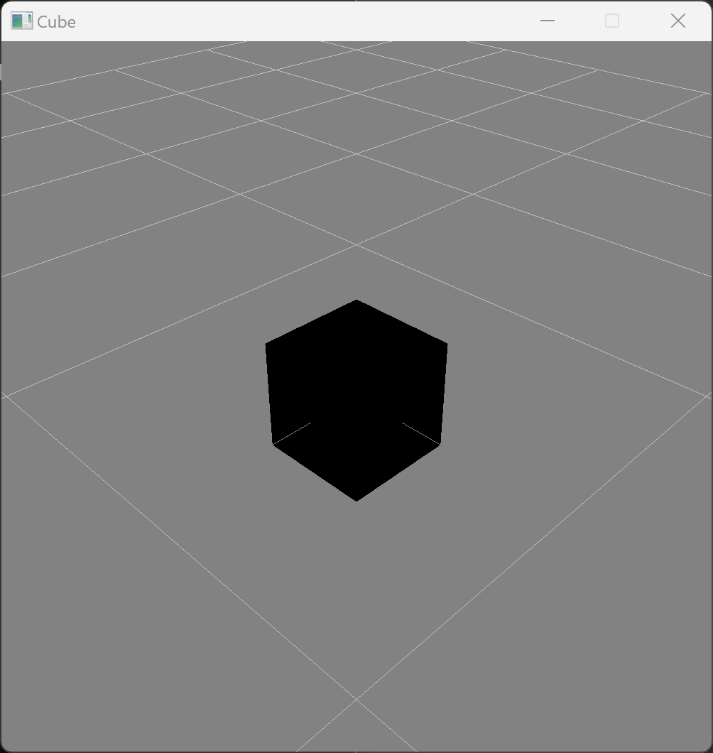
Task: Create a new folder on your computer for the graphics project today, and in the folder save the code above to a file with the file extension .odin Compile and run the code to recreate the image above.
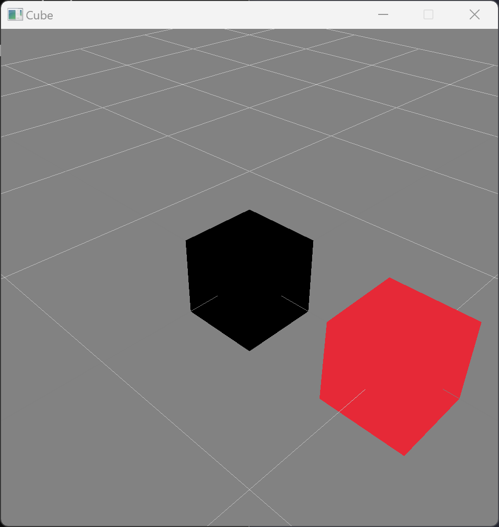
Before we try attempting to create a tetrahedron, we should ask ourselves a basic question: in what direction do the axes point in raylib? We can easily answer this by adding additional cubes to our image. We can draw a red cube at the coordinate (1,0,0) by adding the following line to the drawing section of the code.
rl.DrawCubeV({1,0,0}, 0.5 * {1,1,1}, rl.RED)
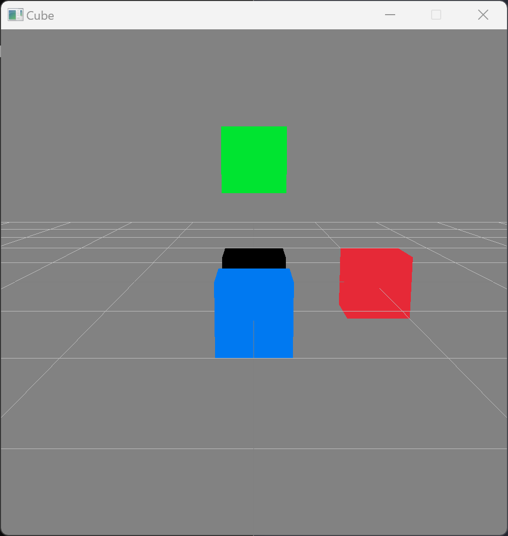
Task: Add a green and blue cube to the scene at the coordinates (0,1,0) and (0,0,1) respectively. Given that the camera is at position (2,2,2) and looking towards the origin, what is the equation of the plane drawn in the background?
Step 2: Animate the camera
Now we have a better understanding of raylib's default coordinate axes, we can change the position of the camera to give us more interesting angles. Changing the position of camera1 from (2,2,2) to (0, 1, 5), for example, produces the following image.
But even with a change in perspective like this, the 3D geometry being drawn is hard to see without the animation being dynamic, so let's make the camera move over time. In lessons 2-10 and 2-11 we added a stopwatch to our Odin code to create a time variable (seconds), which we then used to make our graphics dynamic. By adding in a stopwatch to our code (like in earlier lessons), we can make the vertical position of the camera depend on the time, as illustrated in the video below (click to play).
This is easy to implement; provided we import Odin's standard math library near the top of the file with the line
import m "core:math"
we only need to update the position of the camera inside the main rl.WindowShouldClose() loop before we start drawing with the following line.
camera1.position = {0, m.sin(f32(2 * seconds)), 5}
These is no reason to stop here though. We can also change the horizontal location of the camera. Let's put the camera on a circle, and have it rotate around the objects with time as illustrated below (click to play).
Task: Add in a stopwatch, and as above, animate the vertical position of the camera. Then make the camera loop around the cubes. (Hint: put the camera on a circle parametrized by time.)
Step 3: Draw a tetrahedron
Today, GPUs are pretty great at drawing triangles, and basically every graphics API provides a way to draw heaps of triangles at once. Drawing a tetrahedron only requires that we draw a tiny number of triangles though, so to simplify things, we can draw single triangles in raylib with the following procedure.
rl.DrawTriangle3D({1,0,0}, {0,1,0}, {0,0,1}, rl.YELLOW)
Task: Add the line above to the drawing code, and observe the result. Does anything strange happen?
Bizarrely, the triangle seems to disappear whenever the camera is facing one of the sides. This is due to the order in which the corners of the triangles are specified relative to the camera changing. This is an extremely annoying 'feature' of raylib, but it is too much of a tangent to go into why raylib does this.
For a simple program such as ours, we can fix this issue by doing something fairly crude yet effective: drawing each triangle twice, but with different corner orderings. We can define a simple procedure in Odin to do this for us.
draw_triangle :: proc(a, b, c : Vec3, color : rl.Color) {
    rl.DrawTriangle3D(a, b, c, color)
    rl.DrawTriangle3D(a, c, b, color)
}
We can now just use draw_triangle and not worry about triangles disappearing! Note that in the procedure declaration we've used the type Vec3 instead of raylib's usual 3D vector type (rl.Vector3) since the word Vec3 is significantly more readable and efficient than rl.Vector3. However, we need to tell the compiler that Vec3 is just another name for rl.Vector3. Adding the following line in the top of the file before main does this.
Vec3 :: rl.Vector3
Finally, let's draw a tetrahedron! Using the equilateral triangle calculation we did way back in lesson 2-2, we can define the points of a base of a tetrahedron with
        SQRT3 :: 1.732051
        p1 := Vec3{1, 0, 0}
        p2 := Vec3{-0.5, 0, 0.5 * SQRT3}
        p3 := Vec3{-0.5, 0, -0.5 * SQRT3}
and then use our new procedure to draw it.
draw_triangle(p1, p2, p3, rl.YELLOW)
If we remove the code drawing the cubes and the other triangle, we get something that looks like the following.
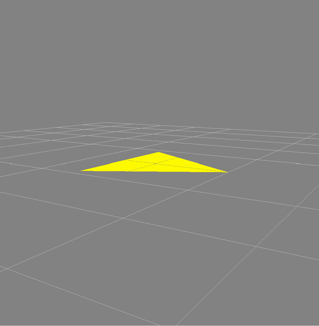
If we can calculate the final coordinate of the tetrahedron, we can then draw the other three sides.
Final Task: Using the code above and the calculation from lesson 2-11, create an animation of tetrahedron like that at the top of this page.