Ithaca High School Math Seminar Lesson 2-8
Date: 2023.11.28
In lesson 2-5 we used a time uniform to make dynamic graphics. Today we'll add in a different kind of dynamism with mouse interactivity. In particular, we'll make the following graphic. (Click the video below to play.)
Step 1: Draw the disk at the mouse position
Let's start with the blue disk from lesson 2-5.
#version 330

uniform vec2 resolution;

void main(void)
{
    float screen_ratio = resolution.y / resolution.x;
    float xc = 2 * gl_FragCoord.x / resolution.x - 1;
    xc /= screen_ratio;
    float yc = 2 * gl_FragCoord.y / resolution.y - 1;

    vec4 color1  = vec4(xc,yc,1,1);
    vec4 color2  = vec4(0,0,0,1);

    bool in_R = xc * xc + yc * yc <= 0.25;

    gl_FragColor = float(in_R) * color1 + float(! in_R) * color2;
}
We want to adjust the code so that the center of the blue disk will be at our mouse position instead of at the center of the screen. This will require us to modify the line which sets in_R. Currently, in_R is set by calculating the square of the distance between the (normalized) position of a pixel and the origin. We can more easily manipulate the geometry of the disk by replacing the line with the following code.
    vec2 pixpos = vec2(xc,yc);
    const float disk_radius = 0.5;
    vec2 disk_center = vec2(0,0);
    bool in_R = distance(disk_center, pixpos) <= disk_radius;
This is a more code, but it is now easy to adjust the center and size of the disk.
Task: Make the disk smaller.
Time to make disk_center dependent on the mouse. If we add the line
uniform vec2 mouse;
below the resolution uniform, and replace the disk_center line with
vec2 disk_center = mouse;
our graphic is now interactive.
Task: Make these changes, then toggle the editor, (View → Toggle Editor) then click / drag with the mouse. What is wrong with the mouse movement?
Looking at the values the uniform is being set to when we drag the mouse tells us what is wrong: by going to the Project tab of the right sidebar, and examining the Mouse parameter (scrolling down if necessary), upon dragging the mouse we see that the values KodeLife sets the uniform too lie between 0 and 1 for each coordinate, and the y-coordinate seems to be inverted. At least one of these issues is trivial to fix.
Task: Invert the y-value of the mouse uniform.
Currently KodeLife is normalizing the position of the mouse to be in region [0,1] × [0,1], while we normalized pixel positions to be in [-1,1] × [-1,1]. As such, we can disable the normalization KodeLife is doing (giving us the pixel coordinates of the mouse), and then in our shader cade we can repeat our normalization calculations.
Task: Turn off normalization of the mouse uniform, and add the following code underneath the pixel position normalization calculations. Set disk_center to use our new normalized mouse position (nmouse) instead of the old one. Test out the new mouse dragging!
    float mousex = 2 * mouse.x / resolution.x - 1;
    mousex /= screen_ratio;
    float mousey = 2 * mouse.y / resolution.y - 1;
    vec2  nmouse = vec2(mousex, mousey);
If everything is working, our fragment shader should now behave like the following when we click and drag the mouse. (Click the video below to play.)
Now the tracking is working, we can add in some smaller disks to orbit the main disk.
Step 2: Add in some animated disks
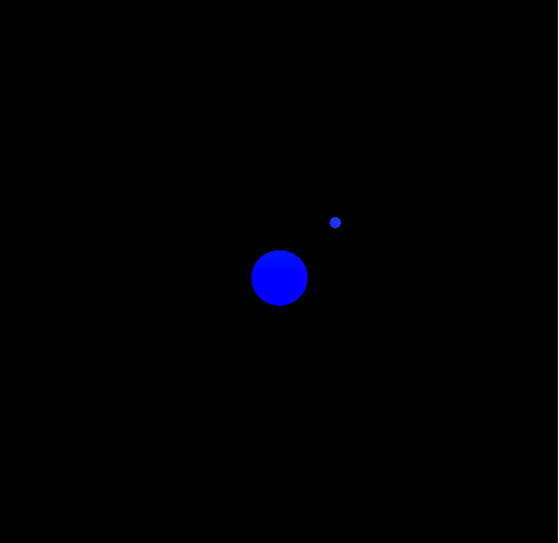
If we wanted to add another disk to the graphic that also moves with the mouse, we can specify the center relative to the other disk instead of using mmouse. This often makes the code easier to read and adjust to get a desired visual effect. For example, adding in
    vec2 small_disk_center = disk_center + 0.2 * vec2(1,1);
    bool small_disk = distance(small_disk_center, pixpos) <= 0.2 * disk_radius;
    bool in_disks = in_R || small_disk;
and then updating the color-setting line to use our new boolean
gl_FragColor = float(in_disks) * color1 + float(! in_disks) * color2;
results in the following image.
Changing the position of the smaller disk is just a matter of changing the direction of the unit vector.
Task: How could we make the smaller disk appear west of the larger disk instead? What about south-west? (Try it.) Position the smaller disk relative to the larger disk in terms of an angle. (Hint: How can a point be specified on the unit circle using trigonometric functions?) Add in a time uniform, and set the angle to be a multiple of the time.
We should now have something like the following video. (Click to play.)
With a couple of additions we can now make the graphic illustrated at the top of this page.
Final task: Add in some other smaller disks and adjust the distances to create an animation like that at the top of this page.
Bonus task: Create your own graphic utilizing orbiting objects. For example, here's a model of the Inner Solar System I made and posted on ShaderToy.